Requirement
In 2018, Hydratron were contacted by a Global defence company to discuss their valve testing requirements in their UK facility. They were testing a large and diverse range of valves that were being used on various types of ship. The valves needed to be tested hydraulically using water with pressures ranging from 1.5bar to 100bar as well as with air up to 7 bar.
Initial Action
The customer originally contacted Hydratron via telephone to discuss upgrading their current test equipment to enable testing to be carried out quicker and safer. Our Technical Sales Engineer travelled to visit the company to discuss how we could support their testing programme.
During the visit it was identified that the user was currently testing their valves using blank flanges and a hand pump which was very time consuming for the operator, not only in set up time but testing times also. It also meant that once the test was complete the valve was still filled with water which had to be removed during a secondary process. It was also identified that some of the valves being tested were fitted with large motors to actuate the valve which we would need to take into consideration when designing the new test rig.
Challenges
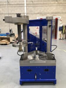
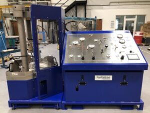
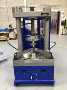
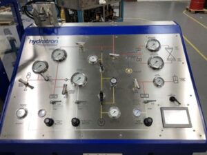
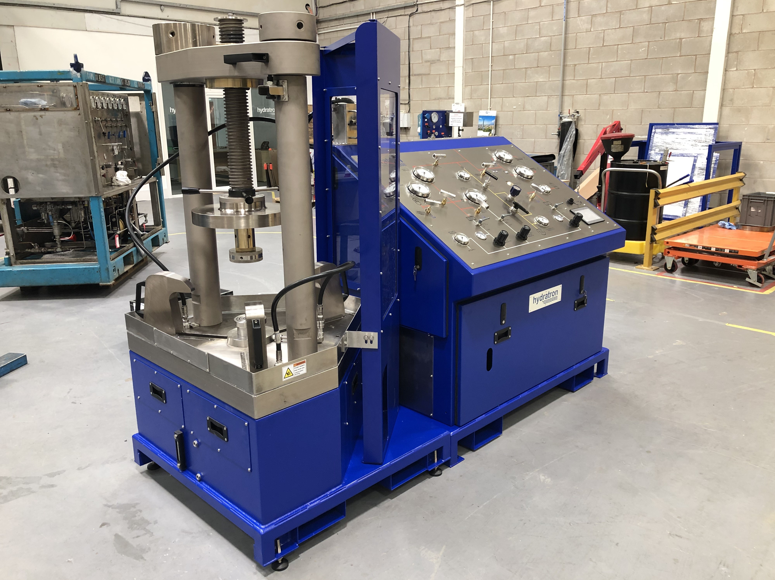
We based this unit on one of our “standard” UVTB’s, meaning the customer would save time as they would no longer have to blind flange their valves, they would also speed up their testing time by using a pre-fill pump and air driven pressure pumps.
To allow the unit to carry out low pressure testing we incorporated an isolation valve, low pressure regulator and bypass on the prefill pump being used within the system. This means that as well as this pump being used to prefill the valves with water prior to test it could also test the valves up to 7 bar. The high-pressure pump could then test from 7 bar up to the required maximum of 100 bar.
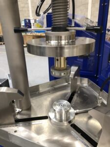
To allow for the testing of the valves with the larger motors we modified our drip tray surround on the unit so that a section could easily be removed if one of the valves with a larger motor was being tested. The “air blow down” in the unit meant that post-test the water in the valve was returned back to tank without any spillages.
Finally, there was also a requirement to test 14-16” valves, however, due to the quantity being tested we deemed it not cost effective to offer this functionality within the unit. We therefore offered them an off-bench testing facility and PLC override which means that the user could test these sizes of valve using the unit but blind flanging them off the test table itself. After a couple of discussions with the client to discuss the proposed solution in-depth, they placed their order.
After two weeks of design development a proposed general assembly drawing created and sent to the client for approval. This was done to ensure that they were 100% happy with what we would be offering before we began to order the parts required to manufacture the job.
Once we had received the approval for the GA drawing, we began procurement and soon started manufacturing the finished article. The unit was delivered to the client before an FAT and training was carried out at their facility.