A large filter manufacturer approached Hydratron with a requirement to design and manufacture a test rig that would be capable of pressure testing two 8″ or larger filters at once whilst simultaneously flow testing a third filter.
Filter Testing Requirements
A Hydratron Technical Engineer visited the customer to see the current filter pressure testing setup that they were using. We also investigated the design of the filters that were being tested. It was important to us to engage with the operators to understand how they are currently carrying out their test and highlight any improvements that could be made.
The process of the sales engineer drafting the proposal was an iterative process. Regular communication with the customer to re-examine points and options available ensured that the final specifications would meet their requirements and exceed their expectations.
Key Features
- Pressure two filters at once up to 3,000 PSI
- Flow Test a third filter from 50-100l/min at 9bar
- Compact design
- Prevent over pressurisation of filters
Pressurising filters for testing
The specification required that two filters could be tested at once to pressures up to 3,000 PSI. There was an additional requirement to flow test a third filter at 50-100 l/min at 9bar
Limited space on the customers shop floor was a tricky design challenge. The customer would be testing up to 3 large filters at once and large IBC’s were being utilised as feeder tanks.
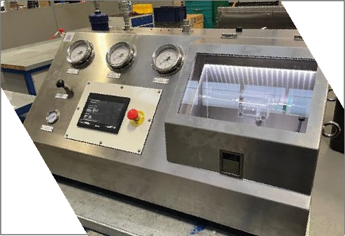
Filter Testing Unit Design
Our engineers developed a filter testing rig that met all of the customers high pressure testing requirements and still retained a small footprint. The use of Hydratron Liquid Pumps made reaching the required test pressures quick and accurately.
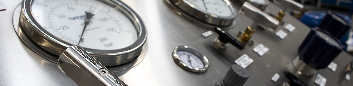
We incorporated an adjustable back pressure regulator, gauge and isolation valve allowing the user to isolate the test piece and set the test pressure using the regulator prior to starting the test. This would mean that there was no risk that the varying test filters could ever be over-pressurised and allows a quick and easy setting prior to every test without components needing adjusting by the operator taking off panels to the unit.
To ensure that the user had clear visibility of the flow that was being applied to the pump, the unit was fitted with high quality digital display unit. To adjust the test pressure an air operated back pressure regulator was installed combined with a panel mounted regulator which would relieve any pressure that wasn’t required.
To overcome the spacing restriction we design a job specific, more compact unit with a safety viewing window above the unit so that the operator could be operating the rig whilst still keeping an eye on how the filters were acting under test. We also mounted the electric pump to the side of the control panel for ease of service when required
The unit was assembled and tested by our engineers before being collected by the customer. It is now a vital part of their busy production process.