A large manufacturer of hoses had completed construction of a new factory and required a dedicated hose testing system that could meet the challenging testing requirements for their hoses.
Custom hose testing requirements
The hoses to be tested ranged from 6mm all the way up to 300mm in diameter and hose lengths would vary up to a maximum of 20m. The hose testing pressures required was from 2 Bar to 100 Bar.
The hose test rig needed to be compatible with a wide variety of hose connections. These included flanges, hammer lugs, Victaulic to BSP, Storz, Kamlock, Bauer and more.
Key Features
- Fast hose test setup times
- Hose testing from 2bar to 100bar
- Compatible with a range of hose sizes and fittings
- Recycling of filtered water to reduce waste
- Steel-walled test chamber with viewing windows
- Remote operation for user safety
Designing the hose test rig
Construction of the drainage/bund area, measuring 12m x 3m, had already commenced when the client engaged with Hydratron to aid with the full design of the system layout, functionality and safety.
The design of the hose test rig had a number of priorities. Foremost was ensuring operator safety throughout the hose testing process. The filling times of larger hoses needed to be sufficiently fast and overall testing time of all hoses needed to be reduced. This would include developing a system that would minimise setup and hose connection time as well as providing accurate control over the test pressure.
Due to the large volumes of water required for testing some of the larger hoses, the client wanted to incorporate a water collection system, including filtration, to recycle the fluid back to the test supply tank.
Building the hose testing system
Hydratron attended client site to work through the hose testing requirements with the client. We inspected the work already completed in relation to the test area and the building work for the bund/drainage area.
The expectations for the sealing and clamping arrangement was an area of acute focus in the early stages. It would require a complete bespoke design clamping system due to the various hose sizes and compatibility with a wide range of hose connections.
Upon inspection of the building work already completed by the client, it was clear that to catch drainage water a complete stainless steel drip tray (12m x 3m) would need to be designed and installed as part of the hose testing system. The design of this would be complex; the full floor area had to be safe for operators to walk and work on when connecting and bleeding hoses. It also needed to be structurally sound to support the test hose; the larger hoses could contain approximately 1400Kg of water when full.
A completely new type of clamping system needed to be designed to hydraulically clamp the hose with the wide size range of 6mm up to 300mm needing careful consideration.
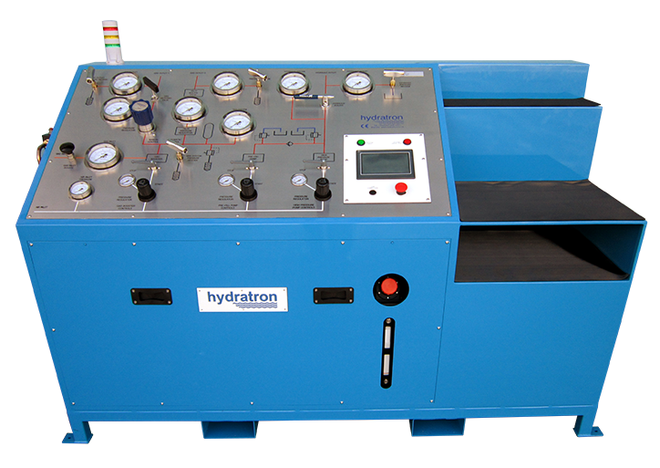
To ensure maximum operator safety the hose test system was designed with capability of carrying out the pressure test remotely.
Installation of the hose test system
The full area inside the test chamber was covered by a custom designed stainless steel drip tray, welded on site and fully sealed. It incorporated the required falls to direct all the water dumped out following testing into a central stainless steel sump. An automatic submersible pump within the sump pumped the water back into the test supply tank via a filtration system. The drip tray was structurally designed to support a mezzanine floor constructed of removable heavy-duty stainless steel grating. This allowed for full drainage and provided a safety working platform for the operators inside the test chamber.
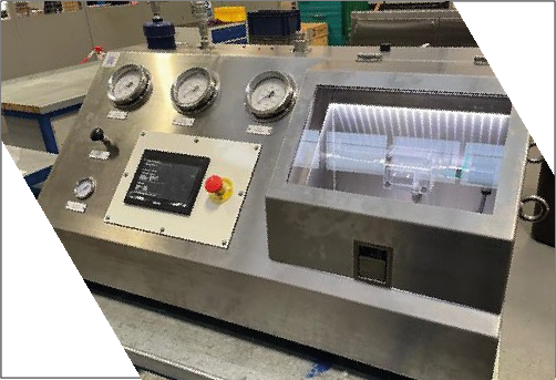
A fully enclosed, 12m x 3 m test area with custom designed steel walls incorporating viewing windows ensured main pressure testing could be completed from a safe location. A double-opening, safety interlocked access door at one end provided full access for loading and unloading hoses. The design and installation of a remote control console to carry out pressure testing outside the test area made it possible for the operator to carry out the pressure testing from a safe location.
Our engineers designed a horizontal, grab type hydraulic clamping system to secure the hose under test which sped up test setup time without compromising on safety. The clamp pressure was monitored to ensure test pressure could never be introduced until the correct clamp pressure had been applied. The test system was also interlocked with the test chamber doors so no test pressure could be generated if the doors are not correctly closed.