A global valve manufacturer approached Hydratron with an enquiry to design and manufacture a relief valve test rig to increase their production capacity and improve current operations. A new rig was required to run pressure tests on their relief valves, including high volume gas ‘pop’ testing and lower pressure gas back-pressure testing.
Relief Valve Test Requirements
The client had a wide range of valves to be tested, including ½” to 8” flanged valves and ½” to 2” screwed valves. The testing pressures required included 6,500psi Water, 6,500psi Gas (pop test) and 800psi Gas (back pressure).
The hydraulic system required a fluid tank, an air operated liquid pump, a large 35 litre accumulator, valves and instrumentation.
Relief Valve Pop Test
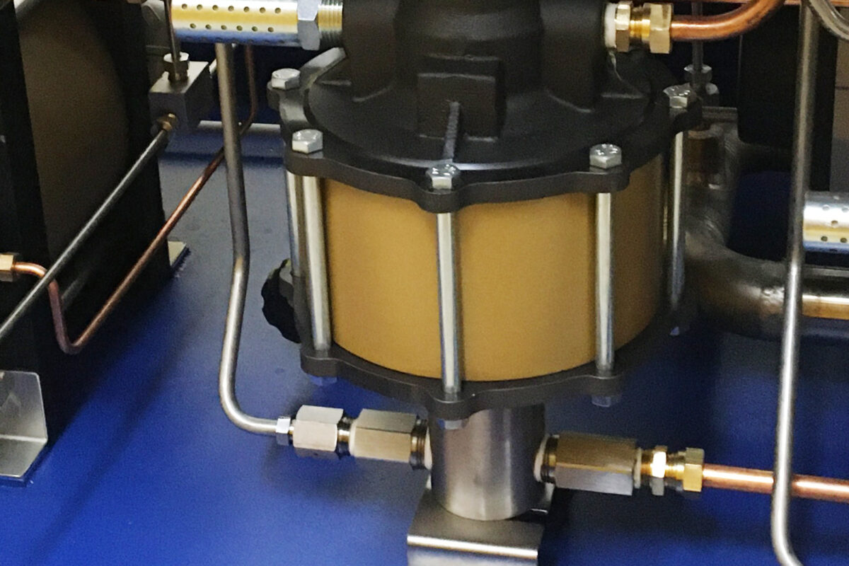
The gas pop test system required a gas booster, a large 50 litre vessel, valves and instrumentation. The gas line would require a direct large bore to the test piece to allow a high release of energy to be applied.
Gas back pressure test
The Gas back pressure test system required a gas reducing regulator, valves and instrumentation.
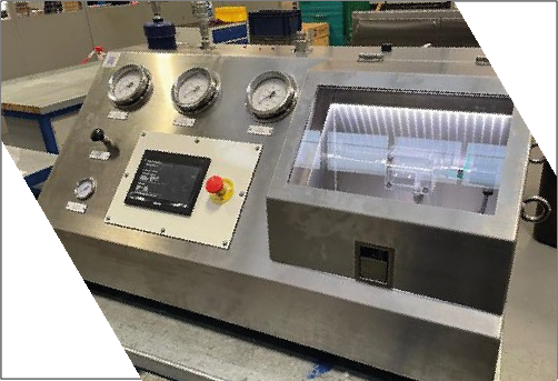
User controls and safety measures
Safety interlocks, to ensure test pressure on any of these lines could not be induced until enough clamp pressure is applied to the valve on test and the enclosure doors are closed. Similarly, the clamps must not be able to be released and the test enclosure doors must lock when test pressure is present.
A touchscreen interface would be included to manage the control of the system. For instance, it must allow the operator to enter the size and pressure of valve they are to test, provide indications of clamp and test pressures and manage all the interlocks. It must also allow for a blow down function to purge the system of water after a water test, prior to a gas test.
Other design considerations
In a physical sense, the unit would have to fit in an existing location of the customer’s, and therefore be no wider than 2,500mm. Furthermore, access would be required at the rear for accessing the valve and providing maintenance access.
Key Features
- Pop test and gas back pressure test functionality
- Capacity for large bore test pieces
- Compact footprint to fit existing location
- Removable maintenance panels
- Single touchscreen interface
- Automatically calculated clamp pressure
- Custom safety interlock system
- Test pressures up to 6,500psi
Understanding critical requirements
A Hydratron sales engineer visited the customers production facility to better understand the requirements of the valve test rig. It was reported back to the design team that their current test utilises the ‘air over water’ method. As this is not the Hydratron standard method, a second visit was necessary so that a Hydratron design engineer could also investigate their current test procedure and determine if the Hydratron standard set-up would be sufficient. It was concluded during the visit that the ‘pencil thick’ stream the operator was looking for when reaching the set point of the relief valve could be adequately achieved with the Hydratron standard circuit which uses the stored energy of a charged hydraulic accumulator. It was also concluded that Hydratron had the design capability to achieve the gas ‘pop’ test using larger bore pipework to the test table.
Relief Valve Test Rig Design Challenges
By working closely with the customer, we were able to identify the main design challenges as follows:-
What size of bore would we require for the customer to achieve the ‘pop’ of their valves?
Research was undertaken on similar systems and current test methods on the customer’s existing rig to try and determine this. We also had to bear in mind the pressure rating, if we went too large it would be more unlikely to be suitable for the 6,500psi pressure. We settled on 1 1/2” stainless steel pipe.
Could we find suitable valves which could maintain the large bore we’d require and be rated to the working pressure we required?
We found some valves however they were actuated ball valves which would rapidly open and concerns were raised about the potential side loading of these valves when acting against pressure. Furthermore, to achieve the pressure, these valves could only be supplied with weld type ends, not screwed.
How to design the safety interlock system?
Using this pipe, we could not use our typical circuitry design for providing the safety interlock to stop test pressure being induced and vent it from the test piece. We therefore had to add multiple pilot operated 2 position, 2-way valves at carefully considered locations to achieve the same result. Not only on the main gas (pop test) and water test lines, but also the back-pressure test line.
How we could also achieve an element of flow control on the gas pop system, if we needed a large bore line to pass the flow for fast release pop testing?
After careful consideration we ended up fitting a flow control valve directly after the pump.
To achieve the air, blow down function, how could we ensure its effectivity?
We had to ensure the air entered the system pipework and the vent exited the system pipework in the most effective locations, to reduce the risk of it not working and purging the lines of water.
How to charge the accumulator and vessels?
Due to the large nature of the accumulator and vessels, we had to utilise a liquid pump and gas booster respectively, each with a high enough performance to charge the accumulator and vessel in an acceptable time frame. This involved assessing flow rates at different pressures and resulted us choosing higher specification pumps to our typical supply.
Relief valve testing rig – designing the solution
A detailed technical proposal and specification was issued to the client, who on review, instructed Hydratron to proceed. A full internal contract review was completed by Hydratron systems engineers, design engineers, production and procurement teams.
Once the circuitry was completed and agreed upon with the customer, it was then necessary to design the physical unit, numerous sheets of the General Arrangement drawings were produced for approval.
Additional design considerations
Ensuring the footprint of the unit could fit into their existing location
Typically, we would always lie the accumulator and vessel horizontally, however, to create the space at the rear of the unit, we needed to stand them up in this case. This led to quite some iterations of the internal layout until we had a workable solution.
Access for maintenance
The layout would allow for a rear door for access to the valve as well as access to the rear panels of the unit for maintenance.
Pipework and clamps
Designing the welded pipework and how this could be connected to the clamp table and large vessel which were supplied with threaded ports proved to be complex. We decided to use Techlok type clamps to allow for the turning for the screwed connections. However, a great deal of thought was required to consider the locations of these clamps to ensure it was not impossible to assemble, and yet would provide the circuitry as previously designed, e.g. if all the pipework was fully welded with screwed ends, it wouldn’t be feasible to screw the test table connection to the pipe.
Maintaining ergonomics with a larger tank
A key design challenge to be resolved was how to fit a larger fluid tank and more panel controls into similar size footprint as existing benches, as well as making way for the welded pipework. This involved raising the height of the tank and raising the height of the test table in order to accommodate it. It also involved clever layout of the control panel, in order to fit a multitude of controls.
Designing a new range of test flanges to suit the larger bore requirement (as well as still being able to withstand the pressure)
There were challenges getting these to suit all the valve sizes (particularly having to step down for the seals of smaller valves), the larger test table spigot and withstand the pressures. The solution involved using a larger O-ring bore seal.
Programming and Electrical Control
The nature of the multiple features in this test bench required a very comprehensive touch screen interface.
Single touchscreen interface
After some initial thoughts and experience, it was deemed we would develop this program to keep all functionality to 1 screen for ease of operation – historical standard test benches used a series of screens, however this added complication for the operator. This was easier said than done however, as we needed to include lists of all valves, many different valves for test and clamp pressures and completion and warning messages such as when the required clamp pressure has been achieved.
Improved clamp pressure setting using calculated values
A formula-based approach to how the clamp pressure is calculated from the size of valve and test pressure to be induced was developed for the unit. Historically this has always been done by set values to cover a range of test pressures, however this new approach suggests optimum clamp pressures, simplifies the program in the longer term and reduces the likelihood of mistakes due to removing manual entries.